Nov 20, 2026
Digital Twin Validation for Defense Propulsion: Fewer Physical Tests, More Confidence
A military propulsion system has to work exactly as specified, every time, in conditions no commercial engine will ever see: battle damage, extreme off-nominal operation, years in storage, or an immediate restart after a fault. Proving all of that through physical testing alone is slow and expensive. Full-scale test campaigns can run for years, and some of these scenarios are difficult or even dangerous to reproduce on a test stand.
A digital twin, a live digital replica of one specific engine that is continuously updated from its sensor data and able to predict its behavior, promises a faster and cheaper path to qualification (Fig. 1). But a digital twin is only useful for that purpose if it can be trusted, and demonstrating that trust to military standards is an engineering challenge in its own right.
This blog examines the requirements for defense propulsion digital twin validation, and the six areas of verification and validation (V&V) needed to assess and establish confidence in their results. It then illustrates the first steps of that process using an RL10A-3-3A rocket engine model developed in AxSTREAM System Simulation and compared with NASA’s published reference results.
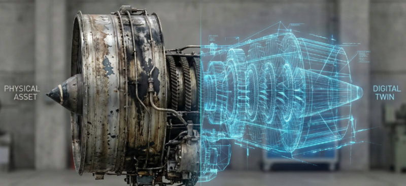
Figure 1. The transition from a physical asset to its digital twin [5]
Key Requirements for Military Equipment and Defense Propulsion Systems
Defense propulsion validation must address more than nominal engine performance. Reliability, survivability, fault tolerance, environmental resistance, and long-term durability all affect whether a system can meet its mission requirements. Table 1 outlines the broader set of requirements that a digital twin can help assess.
Table 1: Main Requirements for Military Equipment and Defense Propulsion Systems [1]
| № | Requirement | Description |
|---|---|---|
| 1 | Reliability | The ability to perform specified functions for a defined period under specified operating conditions |
| 2 | Survivability | The ability to maintain or restore mission capability under damaging effects and failure conditions |
| 3 | Off-nominal operating capability | The ability to function under deviations from nominal operating conditions and under specified failure scenarios |
| 4 | Fault tolerance | The ability to continue performing required functions following the failure of individual components or subsystems |
| 5 | Failure-free operation | The ability to operate without failure for a specified period |
| 6 | Maintainability | The ability to undergo maintenance, diagnostics, and restoration of operational capability |
| 7 | Storability | The ability to retain specified characteristics during storage and transportation |
| 8 | Environmental resistance | Resistance to temperature, pressure, humidity, vibration, shock loads, dust, sand, icing, and other environmental effects |
| 9 | Resistance to combat effects | The ability to maintain operational capability under specified damaging or combat-related effects |
| 10 | Safety | Prevention of hazardous conditions, catastrophic damage, and uncontrolled propagation of failures |
| 11 | Diagnosability | The ability to detect, localize, and identify faults |
| 12 | Prognosability | The ability to assess degradation progression and the probability of future failure |
| 13 | Service life / durability | The ability to maintain required performance throughout the specified service life |
| 14 | Component compatibility and interchangeability | The ability of the system to remain operational following the replacement of specified components and assemblies |
Validating a full-fledged digital twin of a specific propulsion system is not just a matter of verifying the underlying mathematical model. It requires demonstrating that the digital twin accurately represents the behavior of the specific physical asset, is correctly updated using data from that asset, and provides predictions of sufficient accuracy within its defined domain of applicability.
The following six areas of verification and validation (V&V) help build the confidence needed to use digital twin results in qualification.
The 6 Major Verification and Validation Areas for Digital Twins
I. Verification and Validation of the Physical Model
The objective is to assess how accurately the mathematical models incorporated into the digital twin represent the real physical processes at the level of individual components, assemblies, and subsystems comprising the defense propulsion system being developed. Table 2 lists examples of these processes.
Table 2: Examples of physical processes represented in the digital twin
| № | Process | Physics domain |
|---|---|---|
| 1 | Thermofluid processes | thermodynamics; heat transfer; gas dynamics; multiphase flows; fuel–air mixing |
| 2 | Combustion processes | combustion; chemical kinetics; flame stability; combustion-chamber pressure oscillations; combustion-induced instabilities |
| 3 | Turbomachinery and rotor dynamics | compressor and turbine aerodynamics; rotor dynamics; bearing dynamics; vibrations |
| 4 | Lubrication and oil-system processes | oil flow; oil–air two-phase flow; oil–air mixing and entrainment; oil atomization; bearing lubrication; cavitation; hydraulic transients and pressure surges; oil cooling and heat transfer; lubricant degradation; seal leakage |
| 5 | Structural and material processes | thermal stresses; structural deformation; fatigue; wear; material degradation |
II. Validation of the Specific Physical Defense Propulsion Asset
Validation uses ground-test results from a specific engine, along with its design and geometry, actual fuel and lubricant properties, combustion-product characteristics, structural material properties, and as-built injector parameters. It also incorporates the performance characteristics of individual components and assemblies, including compressors, turbines, turbopumps, combustion chambers, and valves.
The digital twin must be configured to represent the specific physical engine rather than an idealized model of the same engine type.
The validation process can be represented by the following chain:
Physical engine → Measurements → Digital Twin → Comparison
The corresponding deviations are then quantified and assessed against predefined acceptance criteria. If the deviations exceed the specified limits, the digital twin is refined and recalibrated, including, where appropriate, by adjusting component and overall system performance or efficiency coefficients.
III. Data Exchange Validation
Unlike conventional standalone simulation models, a digital twin exchanges data with the physical system it represents. Validating this connection is essential to ensuring that the digital twin receives and processes accurate information from the engine.
The following data chain must be validated:
Sensor → Data Acquisition System → Digital Twin → Output
For example, if the physical engine transmits its nozzle stagnation pressure, then it must be verified that the digital twin actually receives 3.265 MPa, rather than 3.180 MPa, due to errors in data conversion, unit handling, transmission delays, or data corruption.
Validation covers sensor accuracy, time synchronization, data update rates, measurement units, missing data, transmission delays, and overall data quality and integrity.
IV. Validation Across Different Operating Conditions
A digital twin cannot be validated at a single operating point. Validation must cover the relevant operating range, including startup, nominal and transient operation, and maximum thrust. It must also account for variations in altitude, temperature, pressure, and fuel flow. For military applications, particular attention should be given to off-nominal conditions that challenge the system’s survivability and fault tolerance.
As a result, a validation domain is established — the range of operating conditions within which the digital twin is considered sufficiently accurate and reliable.
For example: Pc = 2.5–3.5 MPa, Tc = 2600–3600 K, O/F = 4–8.
Here, Pc is the chamber pressure, Tc is the chamber temperature, and O/F is the oxidizer-to-fuel mass ratio; together they define the engine’s operating point. If the model has been validated only within this range, its validity at Pc = 1.5 MPa or Pc = 4.5 MPa cannot automatically be assumed.
In practice, this means repeating the comparison above at other chamber pressures, mixture ratios, and inlet conditions, one operating point after another, until the edges of the validation domain are known. The 1991–1992 Atlas/Centaur start-up failures offer a practical reminder of why off-nominal conditions matter: nitrogen entering an engine inlet line could freeze during hydrogen chill-down and prevent ignition. Thermodynamic modeling helped identify the mechanism [6].
V. Predictive Capability Validation
This represents a higher level of validation.
A digital twin must not only reproduce the measured state of the physical engine but also predict its future behavior.
For example:
The physical engine is characterized by a set of measured parameters:
Pc(τ), Tc(τ),m.(τ), N(τ), Xj(τ),… Pc𝜏, Tc𝜏,m.𝜏, N𝜏, Xj𝜏,…
The flow rate of one of the propellant components changes:
m.(τ)m.𝜏
The digital twin updates its internal state and predicts the resulting behavior of the engine:
Pc(τ+Δτ), Tc(τ+Δτ), N(τ+Δτ), Xj(τ+Δτ),…Pc𝜏+∆𝜏, Tc𝜏+∆𝜏, N𝜏+∆𝜏, Xj𝜏+∆𝜏,…
This ability to reproduce the current state, model its evolution over time, and predict its future state distinguishes a full-fledged digital twin from a conventional computational model.
Thus, the predictive capability is evaluated by comparing:
Prediction → Physical Outcome
VI. Uncertainty Quantification
Uncertainty Quantification (UQ) addresses the question:
How much confidence can be placed in the digital twin prediction, and what is its uncertainty in quantitative terms?
In a complex propulsion system, uncertainty may arise from multiple sources, including random external influences, variability in component parameters, measurement errors, model-form limitations, and stochastic degradation and failure processes.
Table 3 groups these sources into five broad categories that have to be accounted for separately when quantifying confidence in the digital twin’s predictions.
Table 3: Possible sources of uncertainty
| No | Source of uncertainty | Example |
|---|---|---|
| 1 | Randomness in external conditions | variations in ambient temperature; flow turbulence; vibration loads; sensor measurement errors |
| 2 | Variability in component parameters | Two nominally identical engines are never completely identical because of:
|
| 3 | Measurement uncertainty | Sensor measurements and data-acquisition systems introduce uncertainty due to:
|
| 4 | Model-form uncertainty | Even a highly detailed digital twin does not reproduce every physical phenomenon exactly. Uncertainty may therefore result from:
|
| 5 | Stochastic degradation and failure processes | These may include:
|
The goal is to quantify the resulting uncertainty. For example, engineers can quantify it by reporting a prediction interval or probability distribution with a specified confidence level, e.g. a 98% confidence level [2, 3, 4].
Validating an RL10A-3-3A Rocket Engine Model in AxSTREAM
The six V&V areas establish a framework for evaluating digital twin credibility. To illustrate how that process begins, we’ll examine an RL10A-3-3A engine model developed in AxSTREAM System Simulation and compare its predictions against NASA’s published reference results. This example focuses on physical model validation and demonstrates how simulation results can be evaluated against established reference data.
RL10A-3-3A Engine and Model Development
This example illustrates the first two V&V areas: verification and validation of the physical model (Area I) and validation against a specific engine (Area II).
The RL10A-3-3A is a member of the RL10 family of liquid-hydrogen/liquid-oxygen engines (Fig. 2) that has been flying since the 1960s and still powers upper stages today.
It runs on an expander cycle: liquid hydrogen first flows through channels in the walls of the combustion chamber and nozzle, cooling them, and in the process heats up and expands. That hot hydrogen gas spins the turbine, which drives the fuel and oxidizer pumps, and then burns in the chamber with the oxygen. The engine’s own waste heat powers its pumps, so there is no separate gas generator.
The price of this elegance is tight coupling: heat transfer in the cooling jacket sets the turbine power, which sets the pump pressure, which then sets the chamber pressure and thrust. That makes the RL10A-3-3A a demanding and instructive validation case. NASA chose it as a test case for its own engine-modeling tools because of its long test and flight history, and published a detailed model of it in an open report [7]. That model was itself checked against ground-test data from two engines, where all 90 compared values fell within 10% of the measurements, and most within 4%.
The SoftInWay team built a 0D-1D model of the engine in AxSTREAM System Simulation (Fig. 3), using the chamber and nozzle geometry from the NASA report [7], including: turbopumps, valves, the gearbox between the fuel turbine and the oxidizer pump, the combustion chamber and nozzle, and a cooling jacket made of 180 long and 180 short tubes, discretized along the nozzle axis. Heat transfer from the hot gas to the wall is also modeled with the Bartz equation plus radiation from the combustion products, and heat transfer to the coolant with the Mikheyev equation [9].
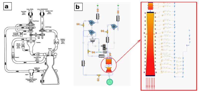
Figure 3. RL10A-3-3A engine schematic (a) [7] and its AxSTREAM System Simulation model [9], with the cooling jacket shown in detail (b)
Cooling Jacket Model Validation
The first check isolates the physics of the cooling jacket (Fig. 4). In an expander cycle, everything else depends on getting this part right. For the known jacket geometry and inlet conditions, the model predicts wall temperature and heat flux along the chamber and nozzle, and these are compared with the results in the NASA report (Fig. 5). The overall picture agrees with NASA’s: heat flux peaks sharply at the throat and then falls off through the nozzle, and wall temperature follows it.
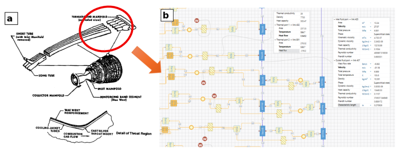
Figure 4. Structure of the RL10A-3-3A cooling jacket, chamber, and nozzle (a) [7] and a fragment of its AxSTREAM System Simulation model (b) [9]
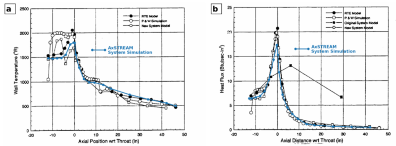
Figure 5. Cooling-jacket wall temperature (a) and heat flux (b) along the engine axis: AxSTREAM System Simulation (blue line) [9] against the models reported by NASA [7]. Axial position is measured from the throat.
Full Engine Cycle Validation
The second check compares the whole engine cycle. In a real qualification program, this comparison would use ground-test data from the actual engine, which is rarely public. So, for an open and reproducible illustration, we’ll compare instead against the NASA report’s engine model, which was itself validated against ground tests. That makes this a check of the physical model and of the comparison workflow, the first building block of digital twin validation, rather than a validation of the digital twin of one specific engine.
In the model, the propellant mass flow rates, inlet pressures and temperatures, and oxidizer pump speed are set to the NASA values, while the turbomachinery performance follows performance maps. What the model has to predict on its own are the combustion temperature, the nozzle stagnation pressure, thrust, and specific impulse. Table 4 shows the result.
Table 4. RL10A-3-3A at its nominal operating point: NASA reference model vs. AxSTREAM System Simulation
| № | Parameter | NASA reference model [7] | AxSTREAM System Simulation | Deviation, % |
|---|---|---|---|---|
| 1 | Combustion temperature, K (°R) | 3,231 (5,816) | 3,299 (5,938) | +2.1 |
| 2 | Nozzle stagnation pressure, MPa (psia) | 3.265 (473.5) | 3.153 (457.3) | −3.4 |
| 3 | Vacuum thrust, kN (lbf) | 73.00 (16,412) | 71.40 (16,051) | −2.2 |
| 4 | Specific impulse, s | 445.6 | 435.8 | −2.2 |
Here, all four parameters agree within 3.5%, and the average deviation is about 2.5%. Together with NASA’s own agreement with ground tests, this gives a layered chain of evidence: ground tests, then the NASA model, then the AxSTREAM System Simulation model.
The remaining differences may be related to differences in the properties of the combustion products and in the steel models used for the nozzle tubes. Whether this level of agreement is enough depends on the acceptance criteria for the intended use of the model.
What this example does not cover:
Data exchange (Area III), predictive capability (Area V), and uncertainty quantification (Area VI) are not demonstrated, and Area IV is covered only at the nominal operating point. Our RL10 cycle model in AxSTREAM System Simulation has also been run at other operating modes, including deep throttling, but the reference data for those modes is not contained in NASA’s open report, so they cannot be compared against a public source here.
The study does, however, give a concrete taste of the uncertainty Area VI deals with: turbopump running torque is known to vary from about 8 to 36 lbf·in between engines (our AxSTREAM System Simulation model uses a constant 20 lbf·in), and the heat-transfer model needed an empirical correction of about 8% to match test data [7].
Conclusions
Validating a digital twin against military requirements is a layered process covering the physical model, the specific hardware it represents, data exchange, operating conditions, predictive accuracy, and uncertainty. Each area contributes to establishing confidence in the model and reducing reliance on physical testing.
The RL10A-3-3A example demonstrates the first steps of this process, with an engine model developed from published geometry and compared against NASA’s reference results, achieving agreement within a few percent. With sufficient validation, digital twins can help engineers investigate failure scenarios, off-nominal conditions, and design changes that would be costly, time-consuming, or dangerous to reproduce through physical testing.
By focusing physical testing on the cases where it is most needed, this approach can reduce the scope and cost of qualification campaigns. AxSTREAM System Simulation provides the 0D/1D modeling framework demonstrated in the RL10 example, from the cooling jacket to the full engine cycle, supporting step-by-step validation of propulsion system digital twins.
References
- [1] U.S. Department of Defense, DoD Instruction 5000.97: Digital Engineering, Dec. 21, 2023. [Online]. Available: https://www.esd.whs.mil/Portals/54/Documents/DD/issuances/dodi/500097p.pdf.
- [2] Digital Twin Consortium, Aerospace & Defense Digital Twin Research and Technology Gap Analysis, Apr. 15, 2025. [Online]. Available: https://www.digitaltwinconsortium.org/publications/aerospace-defense-digital-twin-research/
- [3] T. W. Kennings and D. L. Simon, “Development of a Digital Twin for Electrified Aircraft Powertrain Health Management,” NASA Glenn Research Center, NASA Technical Reports Server, Document ID 20260004592, 2026. [Online]. Available: https://shorturl.at/2Mhza
- [4] A. DiVenti, M. Forsbacka, K. Rainbolt, S. Cornford, and M. Feather, “NASA’s Safety, Reliability, and Mission Assurance Digital Future,” in Proc. 69th Annual Reliability and Maintainability Symposium (RAMS), Orlando, FL, USA, Jan. 23–26, 2023. [Online]. Available: https://ntrs.nasa.gov/citations/20220011839
- [5] Dixon, Pat, “Defining Digital Twin: History, Attributes and Examples,” Automation.com, May 14, 2026. Available: https://www.automation.com/article/defining-digital-twin
- [6] W. Eleazer, “Launch failures: an Atlas Groundhog Day,” The Space Review, Mar. 9, 2009. [Online]. Available: https://www.thespacereview.com/article/1321/1
- [7] M. Binder, T. Tomsik, and J. P. Veres, RL10A-3-3A Rocket Engine Modeling Project, NASA Technical Memorandum 107318, NASA Lewis Research Center, Cleveland, OH, Jan. 1997. [Online]. Available: https://ntrs.nasa.gov/api/citations/19970010379/downloads/19970010379.pdf
- [8] “RL10 rocket engine at the Science Museum, London,” photograph, Feb. 2007, Wikimedia Commons, public domain. [Online]. Available: https://commons.wikimedia.org/wiki/File:RL10_rocket_engine_-_Science_Museum_Feb_2007.jpg
- [9] AxSTREAM System Simulation: RL10A-3-3A validation. SoftInWay documentation. [Online]. Available: https://wiki.softinway.com/v3.10.9/softinway-wiki/axstream-system-simulation/validations/0d-1d-networks/RL10A-3-3A-validation.md
"*" indicates required fields