![]() Apr 1, 2026
Apr 1, 2026
Axial Thrust in Radial Machines: Causes and Mitigation Techniques

When designing high-speed turbomachinery, engineers must carefully consider how many complex parameters interact to ensure smooth and powerful operation. One critical factor is the pressure that builds on both faces of the impeller disk, which can create unwanted axial loads. To prevent this, engineers need to try and balance the pressures along the impeller’s front face and back face using a variety of techniques. In this blog we’ll explore how axial thrust force develops in a radial machine, how to calculate it, and how expeller vanes in AxSTREAM can help control it.
How Axial Force is Generated & How to Calculate it
When a centrifugal machine operates, fluid moves through the impeller and its secondary flow cavities, and the resulting pressure pushes against its surfaces, generating force. The combination of these pressures and forces create a net axial force on the impeller. It’s vital that this net force is reduced in order to limit the thrust load going through the rotor’s thrust bearing. Figure 1 shows how these pressures and forces can be distributed across the front and back faces for optimal operation.
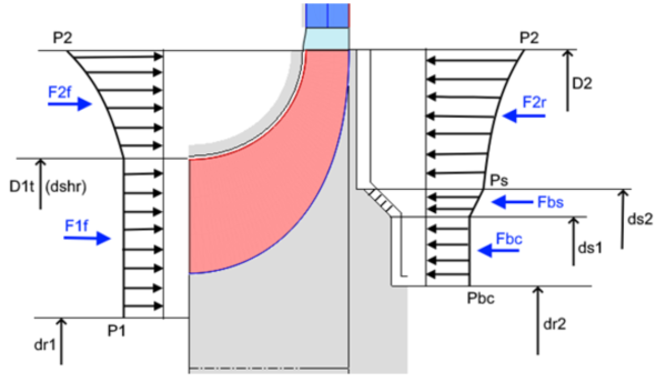
Figure 1. Axial Thrust Force Components Along a Centrifugal Impeller Wheel [1]
Net Axial Force=Fff – Fbf =(F1f+F2f) – (F2r+Fbs+Fbc)
But what happens if the net axial force is too high?
Introduction to Thrust Mitigation Techniques
When the axial force isn’t balanced, the impeller can begin to move axially based on Newton’s 2nd law. Engineers prevent this using several thrust mitigation techniques to keep the impeller in place. These methods include thrust bearings, back-to-back impeller arrangements (for multistage machines), balancing holes, balance disks, balance drums, and expeller vanes.
These techniques can be applied directly to the impeller or to the overall rotor assembly. In this article, we focus on the use of expeller vanes for axial thrust balancing.
Expeller Vane Technique & Benefits for Axial Thrust Balancing
Expellers, also referred to as pump out vanes or back vanes, are small vanes or ribs located along the back face of the impeller. The expeller vanes rotate with the impeller, causing an increase in the circumferential fluid velocity along the back face of the impeller. This increased fluid velocity reduces the pressure near the shaft seal. This reduction in pressure near the shaft seal helps minimize both the pressure difference across the seal and the amount of leakage flow through the seal.
Since the force along the back face is usually greater than the force along the front face, the net axial thrust is reduced—which is exactly what we want! Figure 2 highlights how expeller vanes can help reduce axial force and the shaded area labeled ‘GFKG’ indicates the reduced pressure load along the back face.
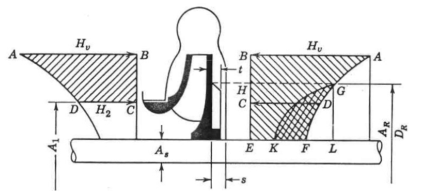
Figure 2. Balancing Axial Thrust Using Expeller Vanes [2]
This is especially helpful when working on a machine where fluid contaminants should be mitigated to avoid escaping through the shaft seals. One thing to consider is that because the expellers are doing work to the back face fluid, the impeller’s power consumption will increase. This slight increase in the machine’s power consumption needs to be accounted for by the design engineer when considering the machine’s drive system.
How to Incorporate Expeller Ribs in AxSTREAM
The impact of adding expeller ribs to the impeller can now be modeled using the latest version of AxSTREAM. A user can specify values like the number of expeller ribs (Zrib), outer rib diameter (drib), and rib height (hrib) directly in the software, while the impeller outlet diameter (D2) and hub disk cavity width (s2) are also used to predict expeller performance. These parameters are illustrated in the figure below and recommendations for selecting expeller geometry can be found in literature [3].
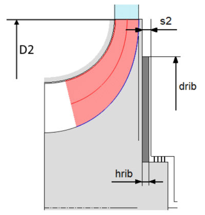
Figure 3. Expeller Geometric Parameters
AxSTREAM uses empirical models to predict how the fluid rotation increases along the back cavity, which enables the prediction of the resulting axial load along the disk. It can also predict the power loss due to the work from the expellers.
The figures below [4] show an example of how expellers affect a high-pressure pump impeller’s performance. Notice the significant reduction in axial thrust force (daf) —a full order of magnitude—thanks to the addition of expeller ribs.
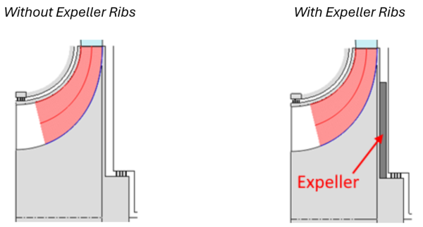

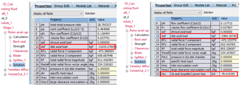
Figure 4. Comparison of geometry and impeller performance without expeller ribs (left column) and with expeller ribs (right column) [4]
The Importance of Balancing Axial Thrust
Balancing axial forces is a critical part of designing radial turbomachinery. By understanding how pressure builds on the impeller and using mitigation techniques like adding expeller vanes, engineers can control axial thrust, prevent unwanted movement, and ensure smooth, efficient operation. With modern software tools, like AxSTREAM, predicting these forces and optimizing impeller design has never been easier—allowing for better performance, reduced wear, and more reliable machines. To test AxSTREAM’s new expeller modelling capabilities, request a software trial here.
References
- SoftInWay Inc., “Disk Axial Load,” 2026. [Online]. Available: https://wiki.softinway.com/v3.10.9/softinway-wiki/axstream-flow-path/axstream-positive-pressure-gradient-machine/nomenclature/solution-rotor-stator-and-other-components/disk-axial-load.md.
- A. Stepanoff, Centrifugal and Axial Flow Pumps: Theory, Design and Applications, New York: Wiley, 1957.
- J. F. Gülich, “Operation of Centrifugal Pumps,” in Centrifugal Pumps, Second Edition, Berlin: Heidelberg, Springer, 2010.
- SoftInWay Inc., “Expeller (Rib Seal) in Centrifugal Impeller in AxSTREAM,” 2026. [Online]. Available: https://wiki.softinway.com/v3.10.9/softinway-wiki/axstream-flow-path/axstream-positive-pressure-gradient-machine/axstream-ppg-documentation/expeller-in-axstream.md.
"*" indicates required fields