![]() Apr 13, 2021
Apr 13, 2021
Hydrogen in Combined Cycles

Explore hydrogen combined cycle power plants, from early concepts to modern zero-emission designs and high-efficiency gas turbine applications.
Update – February 28, 2023: AxCYCLE is our legacy software and has been replaced by AxSTREAM System Simulation. System Simulation was born out of the union of the legacy AxCYCLE and AxSTREAM NET software packages.
Hydrogen is a clean and carbon-free fuel and is considered a key element for energy transition. Renewable power generation by solar and wind is increasing, which requires flexible operation to balance the load on the energy grid with the ability to rapidly adjust the output. Gas turbines with a combustion system for hydrogen operation offers a low carbon solution to support the stability of the energy grid. This provides a solution to the need for energy storage, in the form of hydrogen, and flexible power generation.
Discharging green-house gases and particulates into the atmosphere has an impact on the global climate. With this current trend of increasing awareness towards the environment, alternative fuels are again being examined to reduce the impact of emissions. Hydrogen is perceived as the only long-term solution to global warming concerns. It is also the only fuel that can create large reductions in carbon emissions. There are zero CO2 emissions produced in hydrogen combustion. Hence, NOx emissions are the only remaining concern. Micro-mix combustion is used to implement miniaturized diffusive combustion to combust hydrogen with low emissions. With miniaturized diffusive combustion, local flame hot spots, which are caused by arising stoichiometric conditions of hydrogen, are reduced substantially with an increase in the local mixing intensity. Improvements in the mixing quality provide reduced emissions of NOx with a more balanced flame profile. Micro-mix combustion was also studied with different mixtures of fuels including hydrogen, kerosene and methane establishing an adaptive combustors [1,2].
Power generation systems based on hydrogen could be an important alternative to conventional power systems based on the combustion of fossil fuels. The main effort in the field is oriented towards the use of hydrogen in fuel cells and combustion with gas turbines. Consider the main options for combined cycles based on a hydrogen-fueled gas turbine unit shown in Figure 1.
Basic Simple and Combined Co-generation Cycles
Figure 1. Brayton – Rankine combined cycle
One of the most widely used combined cogeneration cycles is the Brayton – Rankine cycle. This cycle is a symbiosis of the Brayton (simple cycle gas turbine) cycle and the Rankine (steam turbine) cycle.

Figure 2. Typical efficiencies of various types of plants [3]
Cogeneration power plants are designed to generate both electrical power and heat for use in a process application. A typical cogeneration plant uses the waste gases from the gas turbine to produce steam in a HRSG or a waste heat boiler (WHB); these terms are often used interchangeably in various chemical processes. The steam could be used directly in an absorption chiller to produce refrigerated air, or in a steam turbine to drive a cooling system or to produce more power. Water is heated to provide hot water for all types of usage.
Cogeneration systems are also used in petrochemical plants where the prime movers drive compressors to compress process gases. The exhaust heat is used to generate steam for process use, or to operate an extraction, condensing, or a back pressure steam turbine to drive a compressor or pump with the extracted steam then used for a process application.
A typical cogeneration plant in a refinery or a chemical plant generates HP steam which then is used in an extracting condensing steam turbine. It usually extracts part of the steam at a lower pressure for use in various chemical processes; the rest of the steam goes through the second part of the steam turbine and then to the condenser. The steam turbines usually drive separate generators; however, the system can be designed so that both the gas turbine and the steam turbine drive the same generator.
In most chemical plant applications, if the gas turbine is used for power generation it is a single-shaft unit; a twin shaft is used for mechanical drives such as driving a compressor or pump. The gases from the turbine exhaust are normally between 900°F (482°C) and 1100°F (593°C), depending on the turbine efficiency and the turbine firing temperature. The hot gases (approximately 90 lb/s (40.8 kg/s) for a 15 MW turbine to about 1400 lb/s (636 kg/s) for a 200 MW turbine) are piped into a boiler where steam is generated for use as process heat or for use in an extraction or back pressure steam turbine.
Cogeneration plants are also known as combined heat power (CHP) plants and are widely used in Europe where they provide steam heating as well as power to large city centers. Figure 3, below, is a photograph of this kind of plant where the steam is bled after the intermediate-pressure (IP) stage of a three-stage steam turbine, which consists of an high pressure HP stage, an IP stage and a low-pressure (LP) stage.

Figure 3. Steam turbine combined heat and power (CHP) plant [1]
Examples of a Theoretical Zero Emission Combined Cycle
One of the most important programs comes from Japan: the International Clean Energy Network Using Hydrogen Conversion—WE-Net . The WE-Net Program predicts the implementation of the Hydrogen-Fueled Combustion Turbine Cycle (HFCTC) as a new energy source for the power sector. To this end, a configuration and performance study of the HFCTC was conducted. The research was performed in co-operation with the Institute of Energy Utilization, AIST—Tsukuba, Japan. Thermodynamic analysis of the efficiency of power units which use hydrogen as a fuel showed that for power units of more than 10 MW, steam-turbine hydrogen units were the preferred method to fuel cell power units. Experimental H2/O2-steam generators, with capacity of up to 25 MW(t), were created and the peculiarities of their use in steam-turbine hydrogen power units were studied [4].
In light of concerns over CO2 emissions, a novel integrated gasification combined cycle (IGCC) system was proposed with a steam injected H2/O2 cycle and CO2 recovery. A new evaluation criterion for comprehensive performance of the IGCC system was also presented. The results show the new system has a lower energy penalty for separating and recovering CO2, at an efficiency decrease of less than 1 percentage point.
Two options for H2 production through fossil fuels are presented and their performances are evaluated when integrated with H2/O2 cycles. This investigation was conducted with reference to two different schemes, both representative of advanced technology (TIT = 1,350◦C) and of futuristic technology (TIT = 1,700◦C). The high cost of hydrogen production makes thermal efficiency of over 60% HHV (i.e. about 71% LHV) of the energy generation cycle a must in the WE-Net system. Currently, thermal efficiency of the most advanced combined cycles (natural gas fueled) is close to 60% LHV and comparable to 50.4% HHV if hydrogen is used as a fuel.
The efficiency should be increased by about 10 percent points, which is equivalent to an efficiency about 20% higher than the most efficient contemporary power plant units. Meeting this requirement poses a very serious technological challenge, as it is both a qualitative and a quantitative change. Moreover, when increasing the working medium temperature at the turbine inlet to 1,700◦C, it is essential to implement a new, non-traditional approach to both the conceptual design of the system (configuration and working parameters) and detailed construction solutions.
Combined Steam Cycle with Steam Recirculation Prepared by prof. H. Jericha (Technical University of Graz)
![Figure 4. Thermodynamic cycle of the hydrogen/oxygen fueled Graz Cycle plant [10]](https://www.softinway.com/wp-content/uploads/2024/09/Figure-4.-Thermodynamic-cycle-of-the-hydrogen-oxygen-fueled-Graz-Cycle-plant-10.png)
Figure 4. Thermodynamic cycle of the hydrogen/oxygen fueled Graz Cycle plant [10]

Figure 5. Graz Cycle calculation in AxCYCLE
The Graz cycle—proposed by prof. H. Jericha from Technical University of Graz—is an original combination of the Joule and Rankine cycles . Figure 4 and Figure 5 show the cycle as calculated by AxSTREAM® software. In the high parameters area, the Joule cycle is utilized in a semi-closed configuration, coupled with the Rankine cycle, which operates in the low parameters area. The Rankine cycle plays here simultaneously the role of heat sink for the Joule cycle. The hydrogen combustion chamber is the high temperature source of heat. The original idea which distinguishes the Graz cycle from other cycles, is applying the extraction of the partially cooled working medium from the Joule cycle and using it as a working fluid in the Rankine cycle. An increase in efficiency is obtained here due to a significant decrease in the compression work of the working medium in the Joule cycle (steam compressor).
Direct-Fired Rankine Steam Cycle (New Rankine Cycle) was studied in the following variants:
1. Proposed by Toshiba Co., by Convention Called the TOSHIBA Cycle
The Toshiba cycle is one of a group of steam cycles with direct combustion—direct hydrogen fired Rankine steam cycles. The Toshiba cycle is also called the MORITS cycle—Modified Rankine Cycle Integrated Turbine System. It consists of four turbine parts, where two of them—the first and the last (HHP and LPT)—do not have combustion chambers in front. The regenerator (heat recovery boiler) is located before the last turbine part, where superheated steam is produced, Figure 6.
![Figure 6. Schematic Chart of the TOSHIBA Cycle [9]](https://www.softinway.com/wp-content/uploads/2024/09/Figure-6.-Schematic-Chart-of-the-TOSHIBA-Cycle-9.png)
Figure 6. Schematic chart of the TOSHIBA cycle [9]
The Westinghouse cycle is a variant of the steam cycle with direct combustion of hydrogen with oxygen. Compared to the Toshiba cycle, it does not possess the turbine part used in the highest pressure region. It can be classified as a kind of new Rankine cycle with single reheat, Figure 7.
![Figure 7. Schematic chart of the Westinghouse cycle [9]](https://www.softinway.com/wp-content/uploads/2024/09/Figure-7.-Schematic-chart-of-the-Westinghouse-cycle-9.png)
Figure 7. Schematic chart of the Westinghouse cycle [9]
In contrast to the other cycles, the heat recovery steam generator (HRSG) is placed after the last turbine stage group in the low-pressure zone. The layout of the cycle allows another reheat stage to be added before the low pressure turbine stage group. As a result, a very high thermal efficiency of the cycle is achieved. Shown in Figure 8 below.
![Figure 8. Schematic chart of the MNRC cycle [9]](https://www.softinway.com/wp-content/uploads/2024/09/Figure-8.-Schematic-chart-of-the-MNRC-cycle-9-1.png)
Figure 8. Schematic chart of the MNRC cycle [9]
The combustion takes place inside a stream of cooling steam, which reduces the combustion temperature to 1,700◦C. It is also assumed that hydrogen and oxygen at the ambient temperature are available at a pressure level that allows them to be supplied to the combustor. This means that hydrogen would be provided as a cryogenic liquid and that cryogenic energy could be utilized for pure oxygen production in an air-separator unit.
Example of Real Zero Emission Combined Cycle
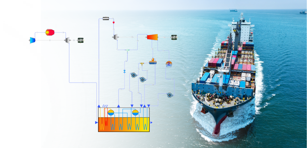
Fusina Hydrogen Power Station is a hydrogen-fueled power station located in Fusina, near Venice in the Veneto region of Italy. It is the first commercial-scale power station in the world fueled by pure hydrogen. The power station is operated by Enel. The Fusina project was launched in 2004. Construction of the power station started in April 2008, and it became operational in August 2009. It was inaugurated on 12 July 2010.[5,6] The plant is located adjacent to the Andrea Palladio Power Station. Fusina Hydrogen Power Station has an installed capacity of 12 MW. An additional 4 MW could be generated in the Andrea Palladio Power Station through the reuse of steam produced by the hydrogen-fueled turbine. The power station is equipped by a General Electric combined-cycle gas engine. The hydrogen is provided from Versalis cracker, and the adjacent petrochemical facility of Porto Marghera [7,8]. Figure 9 and Figure 10 provide an overview of this power system.
![Figure 9. ENEL’s Fusina Zero emission combined cycle [6,7]](https://www.softinway.com/wp-content/uploads/2024/09/Figure-9.jpg)
Figure 9. ENEL’s Fusina zero emission combined cycle [6,7]

Figure 10. ENEL’s Fusina combined cycle calculation in AxCYCLE
Overcoming Current Limitations
Large-scale power plants with pre-combustion CO2 capture, e.g., integrated gasification combined cycles and integrated reforming combined cycles, convert the primary fuel into a hydrogen-rich syngas, then burns it in a combined cycle to achieve the maximum conversion efficiency into electricity. However, the use of hydrogen-rich syngas in gas turbines poses a number of issues. The most important issue to be tackled concerns the mitigation of NOx emissions, which becomes critical due to the very high hydrogen flame temperature. This issue is relevant not only for adapting machines originally designed for natural gas, but also for developing new machines for hydrogen-rich fuels. In diffusive flame combustors, the flame tends to be close to the stoichiometric conditions, and hence, its temperature must be mitigated by diluting the fuel with inert species, such as water (steam) or nitrogen. This dilution causes a significant decrease of the plant’s efficiency. On the other hand, in lean premixed combustors, the flame temperature is directly limited by the large excess of air and no dilution is required. However, realizing a stable premixed hydrogen flame is not straightforward because of its high flame speed demanding high air velocities to obtain short mixing times and high turbulence rates. As a drawback, premixed combustors may suffer from high pressure drops. For this reason, gas turbine manufacturers are currently investigating different combustor geometries in order to obtain the same NOx emissions and combustor pressure drops achieved in natural gas–fueled lean premixed combustors [2].
Interested in seeing how AxCYCLE can be used to model your hydrogen combined cycle power plant? Get in touch by sending us an email at Info@SoftInway.com
References:
- Study of Novel Micromix Combustors to be used in Gas Turbines; using Hydrogen, hydrogen Methane, Methane and Kerosene as a fuel. – Adam Karakurt , Bhupendra Khandelwal , Vishal Sethi , Riti Singh. – 48th AIAA/ASME/SAE/ASEE Joint Propulsion Conference & Exhibit 30 July – 01 August 2012, Atlanta, Georgia .
- Using Hydrogen as Gas turbine Fuel: Premixed versus Diffusive Flame Combustors . – Matteo Gazzani, Paolo Chiesa, Emanuele Martelli, Stefano Sigali, Iarno Brunetti. – Journal of Engineering for Gas Turbines and Power.- MAY 2014, Vol. 136 / 051504-1.- 2014 .
- Combined cycle systems for near-zero emission power generation. -Edited by Ashok D. Rao. – Woodhead Publishing Limited.- 2012.- 338 p.
- http://www.energynomics.ro/wp-content/uploads/2019/06/03.-Cristian-Athanasovici-Kawasaki.pdf
- First Hydrogen Power Plant in Italy”. Alternative Energy. 2009-08-21. Retrieved 2011-10-16.
- Fusina: Achieving low NOx from hydrogen combined-cycle power”. Power Engineering International. PennWell Corporation. 2010-10-01. Retrieved 2011-10-16.
- Jump up to:ab “Enel’s Fusina Hydrogen-Fueled Plant Goes Online”. Power. Tradefair Group. 2009-10-01. Retrieved 2011-10-16.
- Kovalyova Svetlana, Tutt Nigel (2010-07-12). “Enel to start major plant conversion to coal 2011”. Reuters. Retrieved 2011-10-16.
- Hydrogen utilization by steam turbine cycles. – Jarosław Milewski Institute of Heat Engineering Warsaw University of Technology, 21/25 Nowowiejska Street, 00–665 Warsaw, Poland,-Journal of Power Technologies 95 (4) (2015) 258–264 journal homepage:papers.itc.pw.edu.pl
- ADAPTING THE ZERO-EMISSION GRAZ CYCLE FOR HYDROGEN COMBUSTION AND INVESTIGATION OF ITS PART LOAD BEHAVIOUR. – Wolfgang Sanz, Martin Braun, Herbert Jericha, Max F. Platzer Proceedings of ASME Turbo Expo 2016: Turbomachinery Technical Conference and xposition GT2016 June 13 – 17, 2016, Seoul, South Korea
- Mitsugi, A. Harumi, F. Kenzo, We-net: Japanese hydrogen program, International Journal of Hydrogen Energy 23 (3) (1998) 159–165.
"*" indicates required fields