![]() Apr 29, 2025
Apr 29, 2025
Joint Operation of the Turbine and Pump of a Liquid Rocket Engine
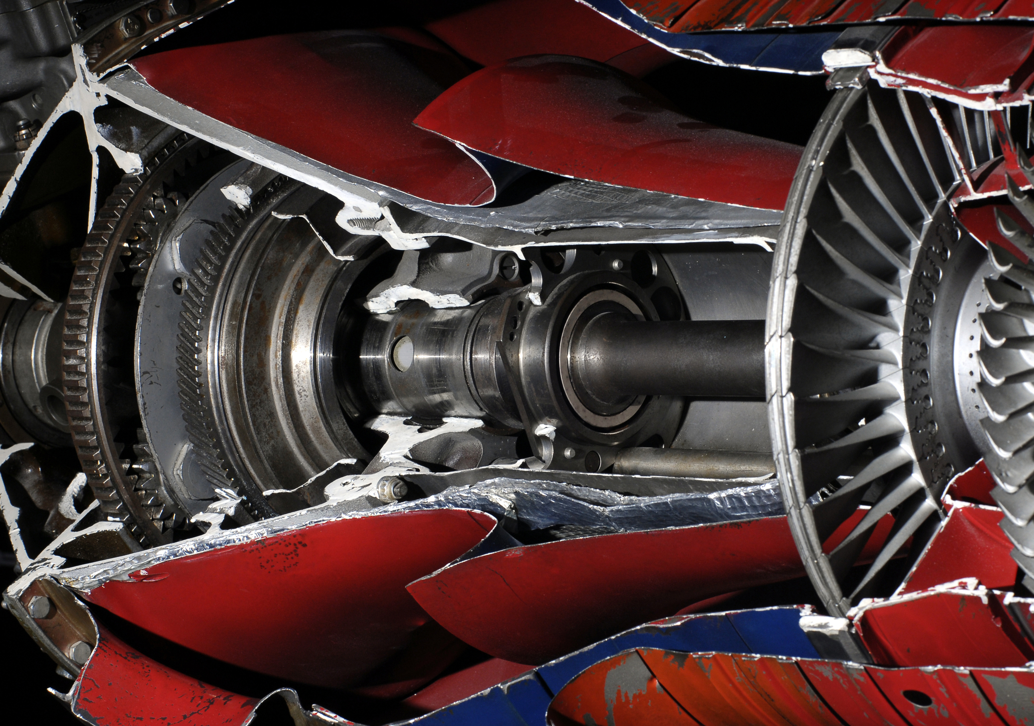
![Fig. 2. External appearance of the turbopump unit (TPU) of a RD0120 engine [3]](https://www.softinway.com/wp-content/uploads/2025/04/TPFig2.jpg "TPFig2")
The turbopump unit (TPU) is often referred to as the heart of the liquid rocket engine design. By the late 1950s, developers realized that pressurized fuel supply systems were only efficient for combustion chamber pressures up to 40 bar. As a result, design bureaus began working to increase engine thrust, specific impulse, operating time, and improve the engine’s weight and size characteristics—a challenge that continues to this day.
The key thermal parameters of the liquid rocket engine (LRE) combustion chamber are the temperature and pressure of the combustion products. Higher temperatures increase the velocity of the combustion products and specific impulse, while higher pressures increase mass flow rate, leading to greater thrust. Higher pressure also enables significant reductions in the size and weight of the combustion chamber (Fig. 1).
![Fig. 1. Influence of combustion chamber pressure on its dimensions [1, 2]](https://www.softinway.com/wp-content/uploads/2025/04/Screenshot-2025-04-29-095821-600x262.png)
Fig. 1. Influence of combustion chamber pressure on its dimensions [1, 2]
![Fig. 2. External appearance of the turbopump unit (TPU) of a RD0120 engine [3]](https://www.softinway.com/wp-content/uploads/2025/04/TPFig2-600x275.jpg)
Fig. 2. External appearance of the turbopump unit (TPU) of a RD0120 engine [3]
While early rocket engines operated within just a few percent of nominal values, modern LREs support a much wider range (40% to 110%). Ensuring stable and reliable turbopump operation remains a critical challenge, however. Global statistics indicate that about 70% of LRE failures are due to TPU malfunctions.
![Fig 3: a. An example of cavitation on the pump impeller [4]; b. Hydrodynamic bearing [5].](https://www.softinway.com/wp-content/uploads/2025/04/Screenshot-2025-04-29-100043-600x217.jpg)
Fig 3: a. An example of cavitation on the pump impeller [4]; b. Hydrodynamic bearing [5].
At first glance, this may seem simple. Given the mass flow rate through the pump, the input and output pressures (which define the required pressure rise), the inlet temperature of the fuel component, and the pump’s efficiency, the required pump power can be calculated. This value must match the turbine’s power. For the turbine, the inlet temperature and pressure are typically known, along with its internal efficiency. By adjusting the gas flow rate through the turbine and the pressure drop ratio, the remaining parameters can be determined. This is the approach used in AxSTREAM System Simulation for TPU design.
STEP ONE
We begin by modeling a turbopump unit. Let’s consider one possible design: a single turbine driving two centrifugal pumps. If the oxidizer and fuel pumps must operate at different angular velocities (often due to cavitation risk in one of the components), a reduction gear is introduced. However, this increases the overall mass and may raise reliability concerns. For simplicity, we’ll examine a configuration that does not include a reduction gear.

Fig. 4. The diagram of the TPU consists of one turbine and two pumps.
STEP TWO
After setting the necessary input and output parameters for each component in Simple Design mode, we define the remaining values. For convenience, watcher elements are added—these allow us to monitor specific parameters of interest during the calculation process. Parameters that need to be defined are highlighted in red, calculated values appear in black, and those used to initialize the calculation are shown in blue. We then verify the power balance: the turbine power must equal the combined power required by the pumps. The efficiency of each component is selected based on the prototype.

Fig. 5. Results of TPU calculation in Simple design
STEP THREE
Once the TPU design is defined and the joint operating point of the turbine and pump is identified, the system’s behavior can be analyzed using performance maps.
For example, a performance map of the mass flow rate of gaseous hydrogen—used as the working fluid for the turbine—can be utilized. By varying two parameters—the pressure ratio and angular velocity—it is possible to identify the optimal balance between them to achieve maximum internal turbine efficiency.
Working with the performance map is straightforward and largely intuitive. An example is shown below.

Fig. 6. Performance Map Workflow
The results of the TPU analysis using performance maps are shown in Fig. 7.
This approach made it possible to identify an operating mode in which turbine efficiency increased from 0.78 to 0.905, while the mass flow rate of gaseous hydrogen decreased from 2.75 kg/s to 2.705 kg/s.

Fig. 7. Calculation result using Performance Map.
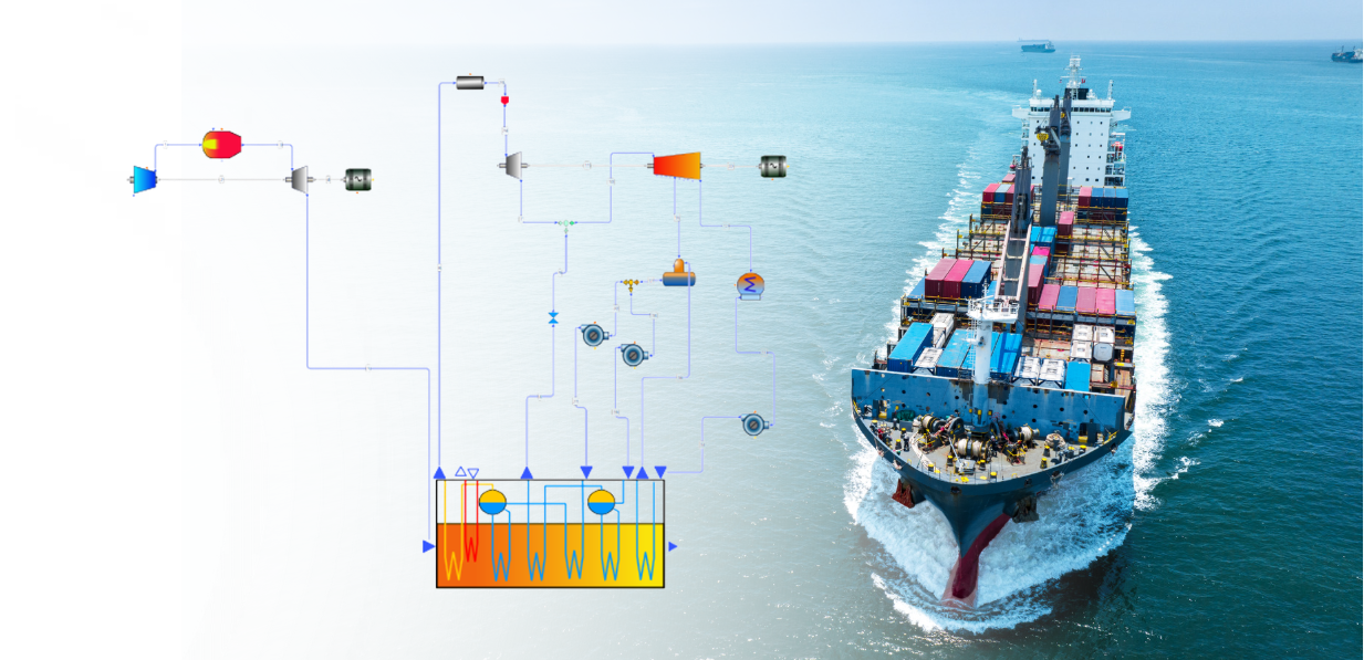
This method can be applied to the calculation of a complex liquid rocket engine configuration using cryogenic hydrogen and oxygen as propellants. The TPU operates on gaseous hydrogen, which is heated as it flows through the cooling jacket of the nozzle and combustion chamber. This setup eliminates the need for a gas generator, significantly reducing the overall mass of the propulsion system.
The TPU includes a gearbox before the oxygen pump, while the hydrogen pump is configured as a two-stage system. In the presented diagram, the pumps operate with incompressible liquid, which reduces calculation time with negligible impact on accuracy.

Fig. 8. Hydrogen liquid propellant rocket engine with a TPU
Once map parameters are set (Fig. 9), results can be generated (Fig. 10).

Fig. 9. Parameters for the Performance Map

Fig. 10. The results of the turbine calculations as part of the propulsion system
of liquid-propellant rocket engine
As a result of the calculations, the operational parameters of the TPU turbine, functioning within the overall diagram of the liquid-propellant rocket engine, were obtained: the flow rate of gaseous hydrogen through the turbine is 2.682 kg/s, the pressure ratio is 1.4, the angular velocity of rotation is 31,500 revolutions per minute, and the internal efficiency of the turbine is 0.75.
Finally, we check the calculation in Simple design mode.

Fig. 11. Verification in a Simple Design
Using CAE tools like AxSTREAM System Simulation significantly simplifies the design and analysis of complex turbopump units in modern liquid rocket engine design. With just a few clicks, engineers can perform detailed calculations, balance turbine and pump operation, and generate complete performance maps—accelerating innovation in propulsion system design.
"*" indicates required fields