![]() Jul 12, 2018
Jul 12, 2018
Organic Rankine Cycles: Low Temperature, High Efficiency

Update – March 1, 2023: AxCYCLE is our legacy software depreciated by AxSTREAM System Simulation. System Simulation was born out of the union of the legacy AxCYCLE and AxSTREAM NET software packages.
Nowadays the scientific community is strongly concerned about problems of efficiency increase and emissions reduction in power generation, ship, and vehicle drives such as internal combustion engines (ICE). A system utilizing waste heat recovery (WHR) is an effective solution for the aforementioned problems.
ORC (meaning organic Rankine cycle, not the scary monsters from Lord of the Rings) is one WHR solution which delivers additional power from the turbine/engine exhaust gas/steam energy. ORC systems operate on hydrocarbon-based fluids which effectively avoid the typical disadvantages associated with water-based steam turbine systems while bringing the advantage of better performance at part load and in non-continuous operation. ORC systems, capable of utilizing low temperature heat sources of 100-200°C, can be designed in compact and modular packages which require very little maintenance.
The design criteria of an ORC system and its components includes finding the maximum possible heat recovery from the available high and low temperature waste heat flows of a turbine or ICE to produce the maximum amount of additional power while decreasing the load on the turbine’s cooling system, under certain restrictions like geometry and cost.
The first step is to design the thermodynamic cycle configuration. Figure 1 is a flow diagram of a dual loop supercritical organic Rankine cycle (SORC) with separate turbines and given design parameters of the components, generated with AxCYCLE™ software, developed by SoftInWay. The cycle consists of 6 heat exchangers, 2 turbines (HPT and LPT), 2 pumps (HPP and LPP) and the condenser. Both turbines operate with the same backpressure – 1.3 bars. The flows of the working fluid (R245fa in this case) are mixed at the condenser inlet and split at its outlet. The temperature – entropy diagram for the presented cycle is shown on Figure 2. The process 1-2-3-4-5-1 corresponds to the high pressure loop operation and the process 10-20-30-40-10 is for the low pressure loop operation. All these can be easily manipulated and obtained with user-friendly interface of AxCYCLE™.
Figure 1. The flow diagram of the SORC with separate turbines
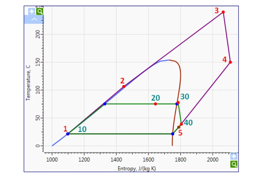
Figure 2. The T-S Diagram for the SORC with separate turbines
In terms of component design, ORC turbines can be of axial, radial inflow and radial outflow configurations. The type of turbine you should select depends on the application. To delve further into the topic, check out SoftInWay’s webinar on “Radial Inflow versus Outflow Turbines – Comparison, Advantages and Applicability” here – http://learn.softinway.com/Webinar/Watch/102
To touch more on one particular configuration, let’s look at radial outflow turbine. The radial-outflow turbine (ROT) design was first invented by the Ljungström brothers in 1912, however it was rarely used due to a number of reasons. One of which was related to the decrease of turbine-specific work due to the increase of the peripheral velocity (uin < uout) while expanding the vapor. Another reason was the usage of steam as a working fluid. It is known from thermodynamics that the expansion of steam is characterized by high enthalpy drops, high volumetric flows and high volumetric ratios. Thus, a significant number of stages is needed to convert the enthalpy drop of the fluid into mechanical energy. Nowadays, turbines for ORC are widely used. Organic fluids have high molecular weight which leads to significantly lower enthalpy drops. Moreover, application of a non-standard design approach which is based on nonequal enthalpy drop distribution between stages allows for the design of radial-outflow turbines with high efficiency; sometimes even higher than equal axial and radial-inflow turbines.
A schematic view of the radial-outflow turbine is shown in Figure 3.
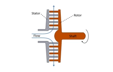
Figure 3. Radial-outflow turbine (schematic view)
Just like axial and radial inflow turbines, radial outflow turbines can also be designed in SoftInWay’s turbomachinery design / analysis tool, AxSTREAM®.
To obtain the most efficient turbine, the design process should be divided into two stages:
- Preliminary design for the feasibility study which shows the influence of the number of stages on the turbine efficiency;
- Detailed turbine design with the optimal number of stages.
Generally, enlargement of the turbine stage number will increase efficiency of the entire turbine. However, since radial-outflow turbine stages are arranged in a radial direction, the circumferential velocity of the blades will increase with a larger radius. This, in turn, can lead to an unwanted supersonic velocity and additional total pressure losses.
Furthermore, a large circumferential velocity leads to significant increase in the bending stresses on the last stages of the turbine. For ROT design there exists an optimal number of stages for a given enthalpy drop which should be determined during the design process.
If you would like to know more about design of ORC cycles and turbines with AxSTREAM® and AxCYCLE™ , please contact info@softinway.com to schedule a demo.
"*" indicates required fields