Apr 24, 2018
Direct Off-Design Performance Prediction of an Industrial Gas Turbine Engine
The modern gas turbine engine has been used in the power generation industry for almost half a century. Traditionally, gas turbines are designed to operate with the best efficiency during normal operating conditions and at specific operating points. However, the real world is non-optimal, and the engine may have to operate at off-design conditions due to load requirements, different ambient temperatures, fuel types, relative humidity, and driven equipment speed. Also, more and more base-load gas turbines have to work at partial load, which can affect the hot gas path condition and life expectancy.
At these off-design conditions, the gas turbine efficiency and life deterioration rate can significantly deviate from the design specifications. During a gas turbine’s life, power generation providers may need to perform several overhauls or upgrades for their engines. Thus, the off-design performance after the overhaul can also change. Prediction of gas turbine off-design performance is essential to the economic operation of power generation equipment. In the following post, such a system for complex design and off-design performance prediction (AxSTREAM®) is presented. It enables users to predict the gas turbine engine design and off-design performance almost automatically. Each component’s performance, such as the turbine, compressor, combustor, and secondary flow (cooling) system, is directly and simultaneously calculated for every off-design performance request, making it possible to build an off-design performance map including the cooling system. The presented approach provides a wide range of capabilities for optimization of operation modes of industrial gas turbine engines and other complex turbomachinery systems for specific operation conditions (environment, grid demands more).
There are many works devoted to accurate off-design performance calculation without mapping utilization; however, their methods are often extremely time-consuming. Therefore, the methods that allow accounting for the advantages of the iteration maps method (relatively short time of calculation) with the 1D calculation of compressor, turbine, and cooling system are of interest. The automation of the off-design GTU parameters search process makes it possible to exclude errors related to transferring large amounts of data for multiple variables.
Simulation of a cooled GTU requires utilization of various 0D, 1D, 2D, and 3D models for calculation of GTU components (compressor, turbine, combustor, cooling system, etc.), presence of efficient data transfer between the models and ability to incorporate custom models, and use logical operations and perform optimizations. The combination of the mentioned tools, methods, models, and scripts connected in logical sequence is essentially a Virtual Gas Turbine Unit (VGTU).
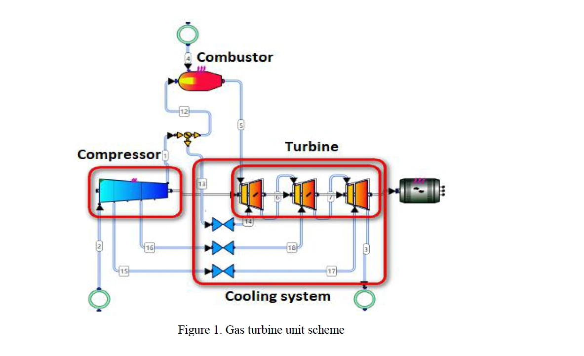
Figure 1. Industrial Gas Turbine Unit with Cooling
Figure 1 is a gas turbine unit system including the compressor, combustor, turbine, and cooling. The scheme of the calculation process is presented in Figure 2.

Figure 2 VGTU operation flowchart
The orange rectangles represent custom scripts. The scripts were added in order to perform additional calculations not available among commercial tools. The yellow blocks represent available computational tools. For the compressor and turbine, it was a streamline solver. For the cooling system, it was a hydraulic network, 1D numerical solver. The pink diamonds represent conditional statements for process control according to a predefined condition.
These blocks enable implementation of loops required to converge required parameters, for example, MFR for each cooling flow. The conditional block could also be used for implementation of alternative paths in the calculation process.
The top diamond on the diagram represents a condition of equal cooling flow MFRs. If the balances of the cooling flow mass flow rates extracted from the compressor and inducted to the turbine do not correspond, the reassignment of cooling flow MFRs is performed. The equality of the turbine inlet MFR and combustor outlet MFR is carried out by the bottom diamond. In this case, the difference in the above-mentioned MFRs leads to the reassignment of turbine inlet pressure.
All of the above calculations were performed automatically. Thus, the capability to simulate off-design performance for any compressor inlet boundary conditions as a user would in a real test facility was achieved.
If you are interested in learning more details of this process, please contact info@softinway.com for a presentation!
Reference:
DIRECT OFF-DESIGN PERFORMANCE PREDICTION OF INDUSTRIAL GAS TURBINE ENGINE, Proceedings of Third Chinese International Turbomachinery Conference CITC, April 12, 2018; Chong Qing, China
"*" indicates required fields