![]() Oct 14, 2016
Oct 14, 2016
Optimizing the Cooling Holes in Gas Turbine Blades

Update – March 1, 2023: AxSTREAM NET is our legacy software depreciated by AxSTREAM System Simulation. System Simulation was born out of the union of the legacy AxCYCLE and AxSTREAM NET software packages.
To increase the overall performance of the engine and reduce the specific fuel consumption, modern gas turbines operate at very high temperatures. However, the high temperature level of the cycle is limited by the melting point of the materials. Therefore, turbine blade cooling is necessary to reduce the blade metal temperature to increasing the thermal capability of the engine. Due to the contribution and development of turbine cooling systems, the turbine inlet temperature has doubled over the last 60 years.
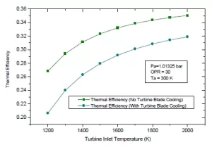
Figure 1: Variations of Thermal Efficiency with TIT [1]
With this in mind, during the design phase of gas turbine it is very important to optimize the cooling flow if you are considering both the performance and reliability. Cooled Gas turbine design is quite complicated and requires not only the right methodology, but also the most appropriate design tools, powerful enough to predict the results accurately from thermodynamics cycle to aerothermal design, ultimately generating the 3D blade.
Different cooling methods that are employed depend on the extent of the cooling required. The cooling flow passes through several loops internally and is then ejected over the blade surface to mix with the main flow. The mixing of the cooling flow with the main flow alters the aerodynamics of the flow within the turbine cascade. The cooling flow that is injected into the main flow needs to be optimized, not only in terms of thermodynamic parameters, but also in terms of the locations to ensure the turbine vanes and blade surfaces are maintained well below the melting surface. The spacing between the holes, both in horizontal and vertical direction, affects not only the surface temperature of the blade, but also the strength of the blade and its overall life.
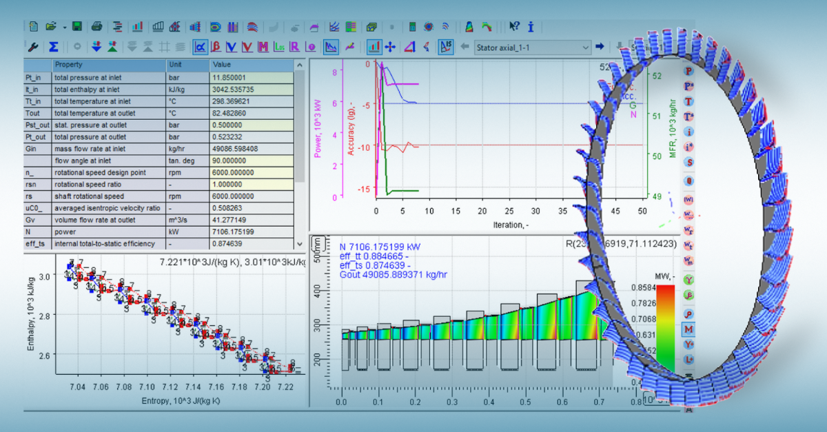
Performing a 3D analysis for optimizing the flow, spacing, and location of cooling flow is computationally expensive. A 1D flow and heat network simplifies the task of not only arriving at the optimal configuration of cooling holes and location, but also in aerothermal design of the gas turbine flow path and generation

AxSTREAM NET™
of the optimized 3D blades with reduced overall design cycle time. Designers are faced with the challenge of simplifying the complex 3D cooled blade and accurately modelling it. AxSTREAM NET™, the module for 1-dimensional flow and heat transfer provides designers options to not only use the different components and models inbuilt in the module but also customize to represent the 3D blade as accurately as possible in a simplified approach
To learn more about how AxSTREAM NET™ can help you optimize the cooling holes in gas turbine blades, please contact us at sales@softinway.com or info@softinway.com.
Source:
[1] Amjed Ahmed Jasim Al-Luhaibi and Mohammad Tariq, “Thermal Analysis of cooling effect on gas turbine blade” International Journal of Research in Engineering and Technology, eISSN: 2319-1163, pISSN:2321-7308"*" indicates required fields