Update – March 1, 2023: AxCYCLE is our legacy software depreciated by AxSTREAM System Simulation. System Simulation was born out of the union of the legacy AxCYCLE and AxSTREAM NET software packages.
The Brayton cycle is the fundamental constant pressure gas heating cycle used by all air-breathing jet engines. The Brayton cycle can be portrayed by a diagram of temperature vs. specific entropy, or T–S diagram, to visualize changes to temperature and specific entropy during a thermodynamic process or cycle. Figure 1 shows this ideal cycle as a black line. However, in the real world, the compression and expansion processes are never isentropic, and there is always a certain pressure loss in the combustor. The real Brayton cycle looks more like the blue line in Figure 1.

(Source: https://commons.wikimedia.org/wiki/File:Ts_Real_Brayton_Cycle_2.png)
The four stages of this cycle are described as:
1-2: isentropic compression
2-3: constant pressure heating
3-4: isentropic expansion
4-0: constant pressure cooling (absent in open cycle gas turbines)
The most basic form of a jet engine is a turbojet engine. Figures 2a and 2b provide the basic design of a turbojet engine. It consists of a gas turbine that produces hot, high-pressure gas, but has zero net shaft power output. A nozzle converts the thermal energy of the hot, high-pressure gas at the outlet of the turbine into a high-kinetic-energy exhaust stream. The high momentum and high exit pressure of the exhaust stream result in a forward thrust on the engine.

(Source: https://en.wikipedia.org/wiki/File:Jet_engine.svg)

The actual T-S diagram for such a configuration of a turbojet resembles Figure 3. Free-stream ambient air, denoted by subscript a, enters the engine inlet that is carefully designed to efficiently decelerate the air to a speed low enough to enter the compressor, at Station 1, with minimal aerodynamic loss. There is stagnation pressure loss in the inlet, but efficient deceleration of the flow raises the static and stagnation pressures at the compressor entrance well above the ambient free-stream static pressure. This conversion of relative kinetic energy of ambient air to increased pressure and temperature in the engine inlet is sometimes called the ram effect. The compressor raises the stagnation pressure of the air further to its maximum value at Station 2, using the power delivered by the turbine. Fuel enters the combustion chamber and is burned with much excess air to produce the high turbine inlet temperature at Station 3. The hot gases then expand through the turbine and deliver just enough power to drive the compressor. The gases leave the turbine at Station 4, still hot and at a stagnation pressure well above the ambient. These gases then expand through a nozzle that converts the excess pressure and thermal energy into a high-kinetic-energy jet at Station 5. According to Newton’s Second Law, the exiting high velocity jet imparts a reaction force (Thrust) in the forward direction. Another factor contributing to the thrust is the excess of the nozzle exit plane pressure over the upstream ambient pressure.

(Source: ENERGY CONVERSION – THE EBOOK by Kenneth C. Weston)
The turbojet cycle is simulated for a specific design operating condition. Based on the application of the turbojet, the cycle design condition can be the Cruise Operating condition, the Takeoff condition, or some entirely different condition. Even though the cycle simulation and component detail designs are performed considering the design point operation, it is important to analyze the cycle performance under all possible off-design operations. An engine is said to be running off-design if any of the following apply:
- Change of throttle setting
- Change of altitude
- Change of flight speed
- Change of climate
- Change of installation (e.g. customer bleed or power off-take or intake pressure recovery)
- Change in geometry
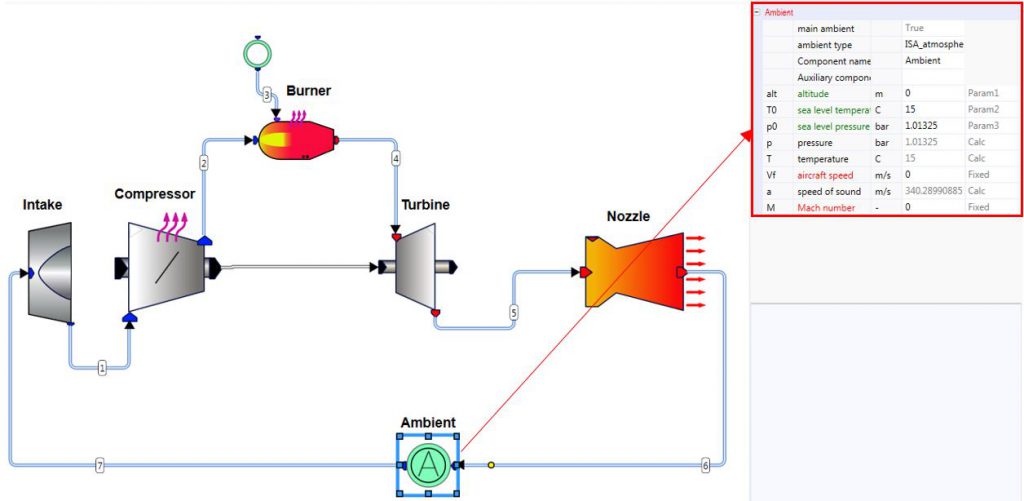
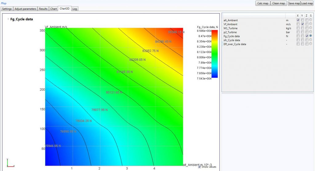
Although each off-design point is effectively a design point calculation, normally the resulting cycle has the same component geometries as that at the engine design point. The numerical simulation of a turbojet cycle is shown in Figure 2b, although performed at the design point, allows one to take in to account most of the off design operating modes listed above. The changes of altitude, flight speed, and climate can all be considered in the Ambient component, shown in Figure 4. In fact, The MAP tool in AxCYCLE™ allows designers to consider any of these parameters as variables in off-design study and to assess the impact of the variations on critical performance factors, such as the gross thrust or specific fuel consumption. Results of one such study are represented in Figure 5, where the flight altitude and flight velocities are varied for off-design analysis. The analysis shows greater gross thrust at high altitude and high flight speeds, considering all the other parameters maintained constant, including the mass flow rate, pressure ratio and turbine inlet temperature. It is also possible to simultaneously vary all these parameters using other multivariable analysis tools in AxCYCLE™.


While performing the analysis of Figure 5, the component performances were assumed to be fixed at all conditions, which is not the case in reality. For performing the off-design analysis of the overall cycle, it is also important to understand and take into account how the individual components (Compressor, Burner, Turbine etc.) would perform under different than designed operating conditions. This requires off-design performance maps, for component geometries simulated under design condition. Performance maps can be obtained either through numerical simulation or through actual experiments on individual components. The component simulations and off-design map calculations can be performed with an integrated component design tool like AxSTREAM®. With AxSTREAM®, it is easy to use the calculated component maps in AxCYCLE™ calculations for more accurate simulation of such cycles under off-design operation (Figure 6).

The example, in Figure 6, considers the off-design performance of the compressor. However, similar methods can be used for other components to consider their off-design performance while calculating the cycle. The process discussed so far allows engineers to simulate most off-design modes of a turbojet cycle, while further integration into AxSTREAM ION™ enables one to incorporate different additional factors into the simulation, such as variable geometry nozzles, bleed flows, power offtakes, etc.
Want to learn more? Contact us at Info@Softinway.com or read about AxCYCLE by following the link – http://www.softinway.com/en/software-applications/heat-balance-design-analysis/


Great sharing of the knowledge earned from undergraduate course at SMME, NUST, Islamabad, Pakistan